
Get in touch with us at our toll-free number 1-800-835-2526 or request a quote here:
Carbon Fiber Containment for Magnetic Rotors at Bunting-Berkhamsted
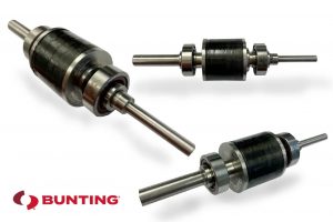
Magnetic rotors are incredibly diverse equipment components, and are used in a wide range of applications. You can find magnetic rotors in motors, generators, alternators, and highly specialized equipment such as Eddy Current Separators. Magnetic rotors spin at extremely high speeds, and this presents the risk of the motors becoming detached from the magnetic carrier. As a result, one of the key design considerations when developing magnetic rotors is the resultant centrifugal force.
Bunting Engineers are Experts at identifying, designing, and manufacturing custom-engineered solutions for high-speed magnetic rotors.
Centrifugal Force
Centrifugal force is defined as “the apparent force that is felt by an object moving in a curved path that acts outwardly away from the center of rotation.” Centrifugal force is commonly confused with centripetal force, its counterpart. While the two are very closely related, centripetal force is defined as “the force that is necessary to keep an object moving in a curved path and that is directed inward toward the center of rotation.”
The key difference between these two forces is that centripetal force is an actual force, while centrifugal force is an apparent force. To use a visual example, if you are twirling a mass on a string, the string is exerting an inward centripetal force on the mass, while the mass appears to exert an outward centrifugal force on the string.
You may be asking—what do these terms mean for magnets mounted to a rotating shaft, operating deep in the heart of a permanent magnet generator, motor, or alternator?
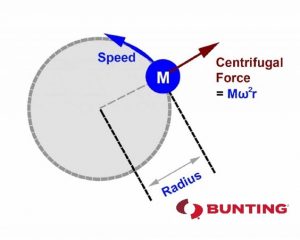
It’s simple—when magnets rotate, they experience a centrifugal load that is proportional to the three variables below:
• The rational speed squared
• The mass
• The effective diameter that the mass spins around
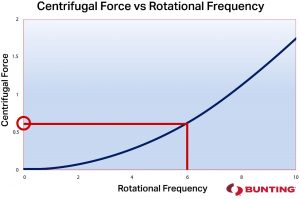
In order to effectively hold the magnets in place when they are rotating, any speed containment system must observe the load that the magnets are generating and apply at least an equal and opposite force when the system is at rest.
Looking below at Graph 1, it is important that during the design phase engineers consider the operating speed of the system, assess the forces to overcome, and then apply that through some means of compression.
Bunting engineers are experts in the design and manufacture of high-speed magnetic rotors, and are equipped with decades of industry experience. Because of this, Bunting engineers excel at identifying, designing, and manufacturing custom-engineered solutions for high-speed magnetic rotors. Examples of these solutions include:
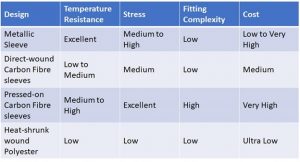
–Metallic sleeves
–Direct-wound carbon fiber sleeves
–Pressed-on carbon fiber sleeves
–Heat-shrunk wound polyester
Specifications for the Different Techniques:
In this review, we will focus on the carbon fiber options with metallic sleeves.
• Design consultancy for magnets, magnetic rotors and magnetic assemblies
Direct Wound Carbon Fiber
For direct wound carbon fiber, the maximum pre-stress possible is 450 Mpa, although this number is dependent on several criteria, including rotor diameter and temperature. It is essential that the method of containment is determined at an early stage. To facilitate this, the Bunting engineering team will undertake an extensive review of the design criteria with the end user of the magnet rotor assembly.
Typically, when using the direct-wound carbon fiber, the greatest challenge is the curing temperature of the carbon fiber. This curing temperature is limited as a result of thermal effects the curing process has on the permanent magnets. For example, certain high strength magnets may have a lower maximum temperature than the carbon fiber’s curing temperature. In this situation, a permanent loss of magnetic performance may occur. Because of this risk, the carbon-fiber wrap technique may be better suited to lower strength magnets that possess a higher temperature threshold.
Bunting engineers have perfected a technique to negate this problem. This technique, referred to as “Post Assembly Magnetization,” first winds carbon fiber onto a rotor that has not yet been magnetized. Then, curing is able to take place at the perfect temperature. This ensures that the right level of thermal support will be provided to the rotor with no losses. Once curing is completed, post-assembly magnetization can take place, magnetizing the rotor in just seconds. While this method requires careful design cooperation and some bespoke tooling, it is extremely effective and efficient.
Pressed-On Carbon Fiber
The maximum pre-stress possible for pressed-on carbon fiber is 1500Mpa, although 1200Mpa is a more realistic value in practice.
Because of this additional pre-stress, other design changes are possible, including increasing the mass by a factor of 3 or 4. However, implementing this kind of design change may not provide the desired results. For example, increasing the depth of a magnet from 10mm to 12.55mm may not substantially benefit the overall design or operating performance of a magnet. Similarly, options such as increasing the diameter of the magnetic rotor may cause other design challenges, including issues such as a larger finished component.
Bunting’s engineering team has found in our experience that increasing the running speed provides the most gains. When working with permanent magnet motors, the optimum magnetic rotor designs are small, fast, and can run hot. By using laminated magnets as a way to reduce eddy current losses at high temperatures, a precision ground magnet surface, and a pre-heat cured pressed-on carbon fiber sleeve, the motor is able to run at very high speeds and maximize the performance envelope. At Bunting, we are also able to post-assembly magnetize these rotors and reduce volume production costs.
• Design and Manufacture of Magnet Assemblies
A rotor that is spinning at 20krpm may generate 10kw and require 300Mpa of containment, but the same rotor spinning at 80krpm may generate 40kw and need 1200Mpa of containment. This is only available through the fitting of a pressed-on carbon fiber sleeve.
Bunting’s engineering team works closely with customers in order to identify the optimum design for a pressed-on carbon fiber sleeve. During this process, Bunting’s engineers also determine the necessary tooling in order to accomplish ease and safety of manufacture and repeatability. As a result, Bunting is able to offer our customers a fully automated pressing process for high volume solutions. This process is complete with an integrated vision system that is able to measure the axial thickness of a sleeve, then press that exact distance so that sleeves are not crushed during the assembly process.
Watching the videos above, you can observe that animations 1 and 2 depict one of our press tools in operation around a 50mm diameter magnet rotor. In the video, it is generating 1200Mpa of press stress in order to allow an operational speed of 100krpm. Animation 1 shows the application of the first layer of carbon fiber, while animation 2 shows the final stage.
At Bunting, we design and manufacture a broad variety of magnets as well as magnetic assemblies. Many of our products are bespoke for specific applications, and our engineers will work with you throughout every step of this process. For further information regarding carbon fiber wrapping of magnet rotors, bespoke magnet assemblies, or magnet designs, please do not hesitate to contact us:
Phone: +44 (0) 1442 875081
Email: Sales.berkhamsted@buntingmagnetics.com
Visit Bunting-Berkhamsted for specialist magnets, magnetic assemblies and magnetising equipment
Visit Bunting-eMagnets for online purchase of Magnets and Magnetic Technology
